Early Version of the Ross-Zentmayer Model, c. 1880
Among the accessories remaining with this microscope are two
objectives each with a canister, a matched pair of eyepieces, a substage polarizer,
an analyzer that mounts above the objective, a stage forceps, and a parabolic condenser
for dark field use.
This binocular microscope is signed on the tail of the base “Ross,
London, 5006.” It is an example of the first version of the Ross-Zentmayer
Model, c. 1880. This microscope is constructed completely of lacquered
brass and measures about 19 inches tall inclined as shown in the photographs.
Height can be further adjusted by engaging the interocular separation controls.
The binocular tubes are mounted on a Lister Limb. The main focusing is by
rack and pinion. The fine focusing is by a micrometer screw that engages a
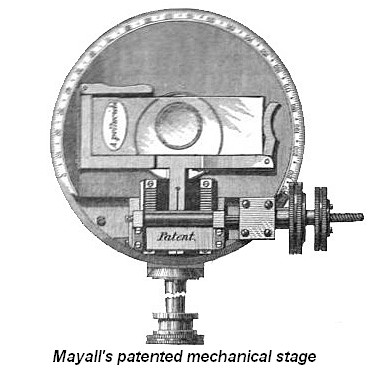
lever mechanism embedded in the limb. The circular rotating stage is calibrated
and is of the Turrell type. It is marked “patent,” which refers to the stage
design patented by Mr. J. Mayall. The stage is attached to the body of the
microscope by a conical fitting that passes through the limb. It allows the
stage to be tilted or removed. It can then be replaced by another stage. The
surface of the stage has a mechanism to lock a slide in place. The substage
incorporates Zentmayer’s swinging motion that was designed to facilitate
oblique illumination. It focuses by rack and pinion and has centering adjustments.
The plane and concave mirrors are on a swinging arm, and its distance relative to the substage
can be varied.
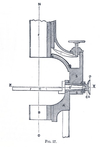
The design of the swinging substage was fully described in Hogg, The Microscope, 14th Edition as follows:
Swinging Sub-stage, or Tailpiece.- The Swinging sub-stage,
although revival of an invention contrived by Mr.
T. Grubb some twenty years ago, has been very
generally adopted, since it is thought by
manufacturers to be an important and useful
addition to the more perfected forms of
instruments. This tailpiece, represented in
sectional elevation fig. 27, consists of
S, the limb carrying the body,
with coarse and fune adjustments;
A, the stem carrying the
sub-stage, B, and mirror.
A is attached to
S by the sleeve or socket
I,. clamped by the nut
J, and on IA may be swung sideways in either
direction to the right or left, either below or
above the stage, the axis of revolution which is
the line XY;
that is, a line in the plane of the object to be
viewed on the stage C, intersected
by the optical axis of the instrument; that is, the
line NO, passing
through the centre of the body and the objects
glass of the microscope The stage
C is also attached to
S by the pin C1,
terminated by the screen C2, which
pin passes through the contre of the socket
I, and moves therein so that the
stage C may readily turn in either
direction in conjunction with or independent of
A, the axis of its revolution
being also the line XY. By this kind of arrangement the
stage C and the stem
A can be set at any angle to the
axis of the microscope, either below or above
XY, intersecting
the plane of the object to be viewed, and
relatively to each other, and when so set the stage
C can be clamped at the desired
angle by the nut D on the screw
C2 acting on S
and the collar K.
This microscope, introduced in 1878, was the initial design of the Ross-Zentmayer microscope. Early on, there was some criticism of the design primarily about the shape of the
base. It was felt that it didn't allow sufficient stability under certain
conditions. Read what William Carpenter wrote in the 8th Edition of The Microscope
and its Revelations about this presumed defect. Accordingly, this design was short lived resulting in Ross producing an Improved Version to correct the shortcomings of the original. As a consequence of this, the original version is far less common than the improved version.