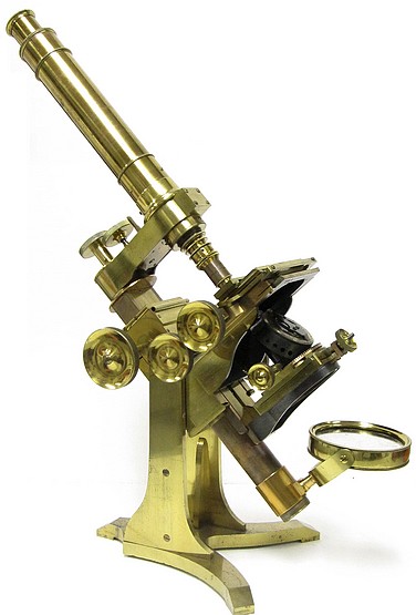
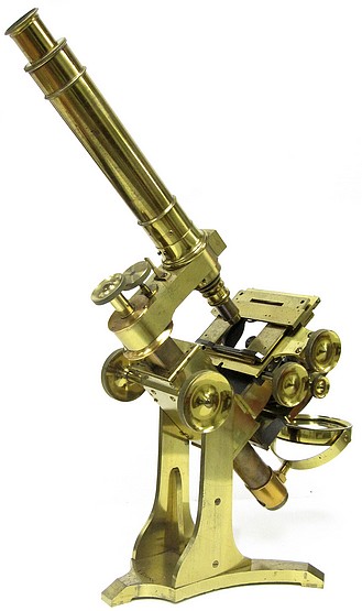
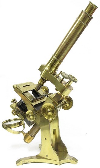
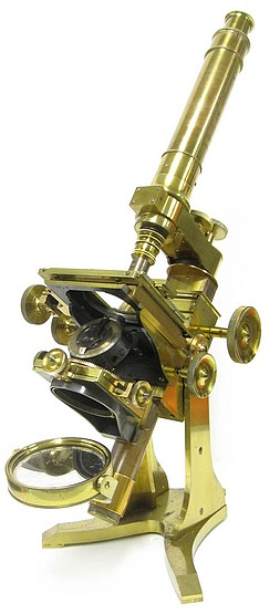
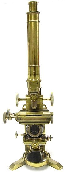
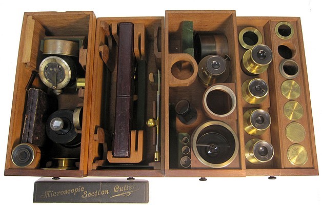
This is a fine example of the classic bar-limb design first introduced by Andrew Ross in 1843. It incorporates a number of improvements of the original model.
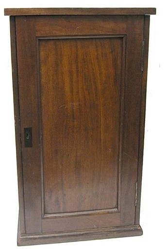
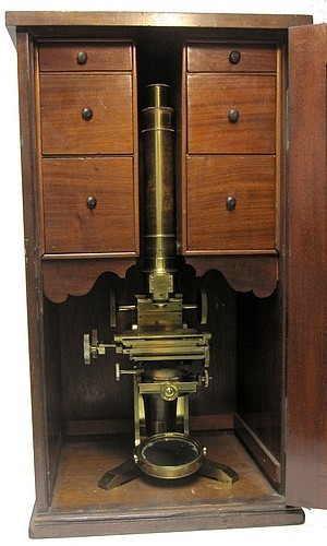
The accessories are stored in the lower four drawers of the case (the upper two drawers are for slides). They consist of four eyepieces, four Ross objectives with their brass canisters, substage polarizer, eyepiece analyzer, two live boxes, glass trough, camera lucida, hand forceps, stage forceps, stage-mounted bulls-eye condenser, substage wheel of apertures, substage dark-well holder with three dark-wells, mechanical eyepiece micrometer, a large leather box with glass pipettes, another leather box with a sectioning razor, a small leather box with a selenite slide, and one with a quarter wave plate (marked R&J Beck), a simple lower power substage condenser, and a fine example of Gillett's condenser, which bears a Ross signature; additionally, there are some other odds and ends/adapters.
The following was extracted from Quekett's Practical Treatise on the Use of the Microscope, third edition, 1855. It is quote from Andrew Ross's description of the improved form of the 1843 design:
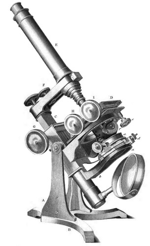
This instrument, first described by Mr. Ross in the London Physiological Journal, in 1843, is represented by Plate 1; and as no language of the author could convey so good an idea of its construction as that given by Mr. Ross himself, his own words will here be quoted :
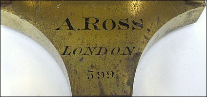
"The mechanical construction represented in Plate 1, is derived from a practical acquaintance with the various improvements made in the microscope for the last twenty years. The general arrangement, which is properly the province of the mechanic, has been contrived to obtain the utmost freedom from tremor, and to afford the greatest facility in using the various movements, while the extent, direction, and number of these have been collected from the experience of the most indefatigable observers in all the various branches of microscopic inquiry. Nearly six hundred instruments have been made on the plan here represented, and as but slight alteration or addition in detail, has been found necessary for the accomplishment of all the modes of microscopic investigation at present employed, the mechanical structure of the microscope stand may be considered thus far established
The optical part also has arrived at such perfection, that points or lines, whose distance is such that their separation is bordering on interfering with the physical constitution of light, can be distinctly separated; thus ensuring a reality in the appearance of objects, where the minuteness of their detail approaches the natural limit of microscopic vision.
A are two uprights, strengthened by internal buttresses, mounted on a strong tripod, B, at the upper part, and between the uprights is an axis upon which the whole of the upper part of the instrument turns, so as to enable it to take a horizontal or vertical position, or any intermediate inclination, such, for instance, as that shown in the plate. This moveable part is fixed to the axis near its centre of gravity, and consists of the stage, D, the parallelopipedon bar and its socket shown at C, with its arm, which carries the microscope tube, E, and the mirror, M. The stage, D, has rectangular movements, one inch in extent, on dovetail slides, and is moved by a pinion and screw connected with the milled heads, H I, and it also has the usual appendages of forceps to hold minute objects, and lens to condense the light upon them. The parallelepiped bar, together with the arm and microscope tube, is moved by the milled heads at G, and a more delicate adjustment of this optical part is effected by the milled head F. The other milled head, K, fixes the arm to the parallelepiped bar. The outline of the structure, as before observed, has been arranged to obtain, first, the utmost freedom from tremor, and, secondly, to afford the greatest facility in using the various movements.
In experimenting to obtain the first of these conditions, I suspended the moveable part of the instrument near the centre of gravity, and employed the inverted pendulum (an instrument contrived to indicate otherwise insensible vibrations) to arrange the form and quantity of material so as to produce, as nearly as possible, an equality of vibration throughout the whole instrument; hence the object upon the stage and the optical part vibrating equally, no visible vibration is caused. The arrangement for accomplishing the second condition is, first, that the whole movements should be as near the base of the instrument as is consistent with the greatest proximity among themselves; then the milled heads at G for moving the parallelepiped bar, and the fine adjustment for the optical part, should be moved by the left hand, while the heads H and I, for the movement of the stage, should be worked by the right hand. The other milled head, opposite G, is convenient when the right hand may be unemployed with the stage movements. The positions of the milled heads, H and I, are extremely convenient, as the middle finger may be placed under H, and the fore-finger under I, and the thumb passed from the one to the other in the most natural and easy manner. The left hand is also readily shifted from the milled head at G, to employ the fore or middle finger to move the screw head F. This head is connected with a screw and lever, which makes one revolution of it move the optical part one three-hundredth of an inch. This arrangement affords an elastic movement to the end of the tube, as a guard against injuring the glasses or the object under examination.
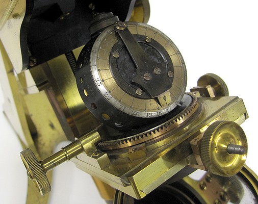
By means of the milled head at e, the whole stage, D, carrying the object may be rotated one-third of a revolution (note: the example presented herein does not incorporate the milled head e, but instead, the stage can be rotated by hand) underneath the object stage, D, is the secondary stage, a a, and b, which consists of a cylindrical tube, having a rotary motion by means of the milled head, c, also a rectangular adjustment which is effected by to screws, one on front at d, and the other on the left side of the frame. This tube receives and supports the various illuminating and polarizing apparatus and other auxiliaries which are placed underneath the object The cylindrical tube and its frame are affixed to a dovetail sliding bar, and can be easily removed for conveniently attaching the various apparatus. This sliding bar fits into a second slide, which, by means of a milled head on the left of the general stage moving a rack and pinion (not to be seen in the plate), serves to regulate the distance of the apparatus from the stage. The condenser of Mr. Gillett, hereafter to be described, is represented by, as being fitted into the tube, a."
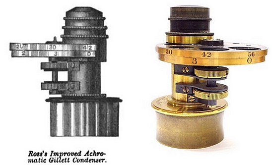
The following description of Gillett's condenser was extracted from The Microscope by J. Hogg, 1859:
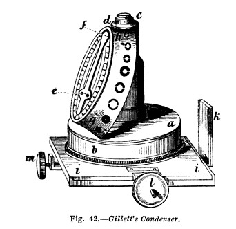
Gillett's Illuminator, or Condenser. The advantages of employing an achromatic condenser were first pointed out by Dujardin, since which time an object-glass has been frequently but inconveniently employed; and more recently achromatic illuminators have been constructed by most of our instrument makers. Some years since, Mr. Gillett was led by observation to appreciate the importance of controlling not merely the quantity of light which may be effected by a diaphragm placed anywhere between the source of light and the object, but the angle of aperture of the illuminating pencil, which can be effected only by a diaphragm placed immediately behind the achromatic illuminating combination. Such a diaphragm is represented in fig. 42, manufactured by Mr. Ross: it consists of an achromatic illuminating lens c, which is about equal to an object-glass of one-quarter of an inch focal length, having an angular aperture of 80 degress. This lens is placed on the top of a brass tube, intersecting which, at an angle of about 25 degrees, is a circular rotating brass plate a b, provided with a conical diaphragm, having a series of circular apertures of different sizes h g, each of which in succession, as the diaphragm is rotated, proportionally limits the light transmitted through the illuminating lens. The circular plate in which the conical diaphragm is fixed is provided with a spring and catch ef, the latter indicating when an aperture is central with the illuminating lens, also the number of the aperture as marked on the graduated circular plate. Three of these apertures have central discs, for circularly oblique illumination, allowing only the passage of a hollow cone of light to illuminate the object. The illuminator above described is placed in the secondary stage i i, which is situated below the general stage of the microscope, and consists of a cylindrical tube having a rotatory motion, also a rectangular adjustment, which is effected by means of two screws I m, one in front, and the other on the left side of its frame. This tube receives and supports all the various illuminating and polarising apparatus, and other auxiliaries which are placed underneath the object. The tube and its ftame are affixed to a dovetailed sliding bar k, which can be easily moved up or down, or taken off for conveniently attaching the various apparatus. This sliding bar fits into a second sliding bar, which, by means of a milled-head screw, moving a rack and pinion, regulates the distance of the apparatus from the stage.
Elsewhere in this collection is an example of Ross's Improved Gillett Condenser.
A later example of a large Ross No.1 is also represented in this collection. For other early microscopes made by Andrew Ross and a short history of the Ross firm see: this