The following article appeared in The Monthly Microscopical Journal-Transactions of the Royal Microscopical Society, 1870:
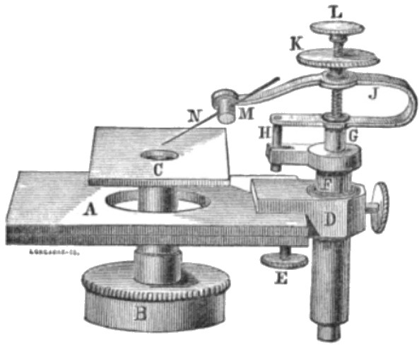
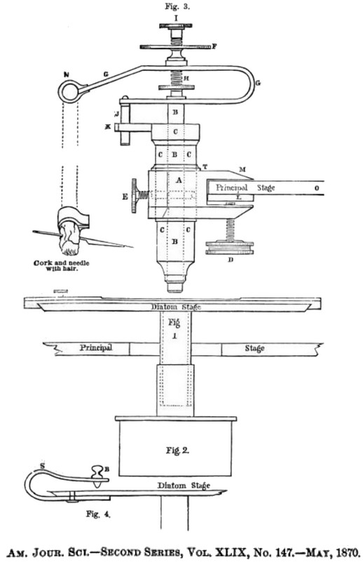
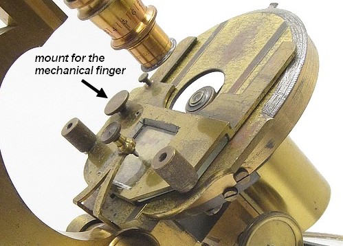
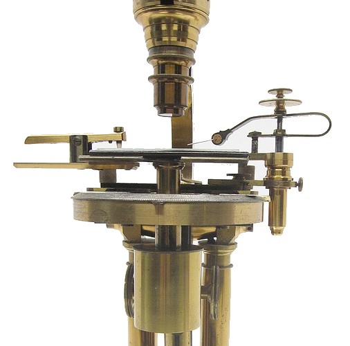
A New Mechanical Finger for the Microscope.— Mr. J. Zentmayer gives the following description of a recent invention by him in the ‘Journal of the Franklin Institute’ for May: — In the study of diatoms it has been long desired to find a substitute for the clumsy fingers of the human hand to do the delicate work of picking up rare and valuable diatoms detected by the microscope, and to transfer them to a glass slide for preservation. Prof. H. L. Smith, well known by microscopists as the inventor of several valuable accessories to the microscope, first presented us with a very ingenious little instrument of that kind. Messrs. John H. B. Latrobe and George Dobbin, of Baltimore, two expert microscopists, had in use for some time one of these instruments, but found it difficult to work it; and as the instrument was exceedingly well made, this proved that its construction was too complicated to give the firmness required in picking up a shell less than the thousandth part of an inch in length, and of which a single ounce of ocean sand contains, sometimes, many millions. Mr. Latrobe invited mo to design and construct for him an instrument for this purpose. The instrument requires many adjustable movements, and each of these increases its liability to shake and spring. So I made it my object to utilize such movements of a first-class microscope stand as are not essential for other specific operations, as parts of the new finger. I found in the movements of a mechanical or sliding stage the main movements required in the finger, and so attached the apparatus to the mechanical stage. This gave me two of the most important movements, with a firmness and with dimensions of parts for which, otherwise, there would be no room. This step, however, made it necessary to provide for another stage; but as there is never a higher power than a 2/3rds employed with such an apparatus, a plain stage with some simple arrangement to hold the slides would be found quite sufficient — such a one was therefore arranged. The cut represents the finger attached to one of my large microscopes. A is the top plate of the mechanical stage; the circular plate is omitted. The cap B is fitted to the lower body below the stage, into which cap the new sub-stage C is fastened by a narrow tube, wide enough to admit illumination from the mirror. As the lower body is movable up and down by a rack, another movement is gained which is necessary to accomplish our result. The difference of the size of the aperture of the stage and the diameter of the tube which connects the sub-stage with the cap A is equal to the movement of the mechanical stage, and this is found more than sufficient. D is the clamp by which the fìnger is attached to the stage by means of the screw E. A steel cylinder G is nicely fitted into the top and bottom of the tube F, leaving room inside for a light spring to press the steel cylinder upwards. To prevent turning, the spring J is provided, at H, with a steel pin accurately fitted into the fork at the top of the tube F. By turning the nut K the spring J is elevated and depressed, giving nice adjustment to the needle N, in case the finger is to be attached to a microscope not having rack-movement to the cap B, to bring the end of the hair and the object in close approximation. The end of the spring J forms a little ring, with a screw cut inside, into which a cork M is screwed to receive a needle N, to which a hair is fastened by wrapping gum-paper around. Turning the cork facilitates the adjustment of the hair to the proper inclination. A slight pressure on the button L brings down the hair, and the spring, inside of F, instantly lifts it again when the pressure is removed. the tube F turns in the clamp D in order to adjust the hair and cork more conveniently, and when brought back again it is tightened by a set screw. Complicated as it may appear, only one movement is added to the microscope stand by this instrument, the one, viz. which gives the vertical motion. When the apparatus is to be used the material you want to select from is placed on the sub-stage C and focussed, then the point of the hair is approximately brought over the selected object by means of the stage movements and turning of D ; this brings the hair nearly in focus too, because it is almost in the same plane with the object. We next adjust the hair precisely over the selected shell, press down the button L, and the shell will adhere to the hair. Now we remove the slide with the material and substitute a glass slide, moistened by breathing on it, and having brought it in proper position, briskly dip down the button L again and the shell will be deposited on the glass slide. As the mechanical stage has a graduated indicator, the finger may be moved along regularly, and shells may be placed at equal distances in lines. After the cover-glass is carefully placed over it, then Canada balsam may be run in by capillary attraction without disturbing the position of the shells.